Fundamental Electrical Isolation and Current Leakage Prevention
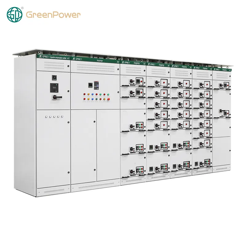
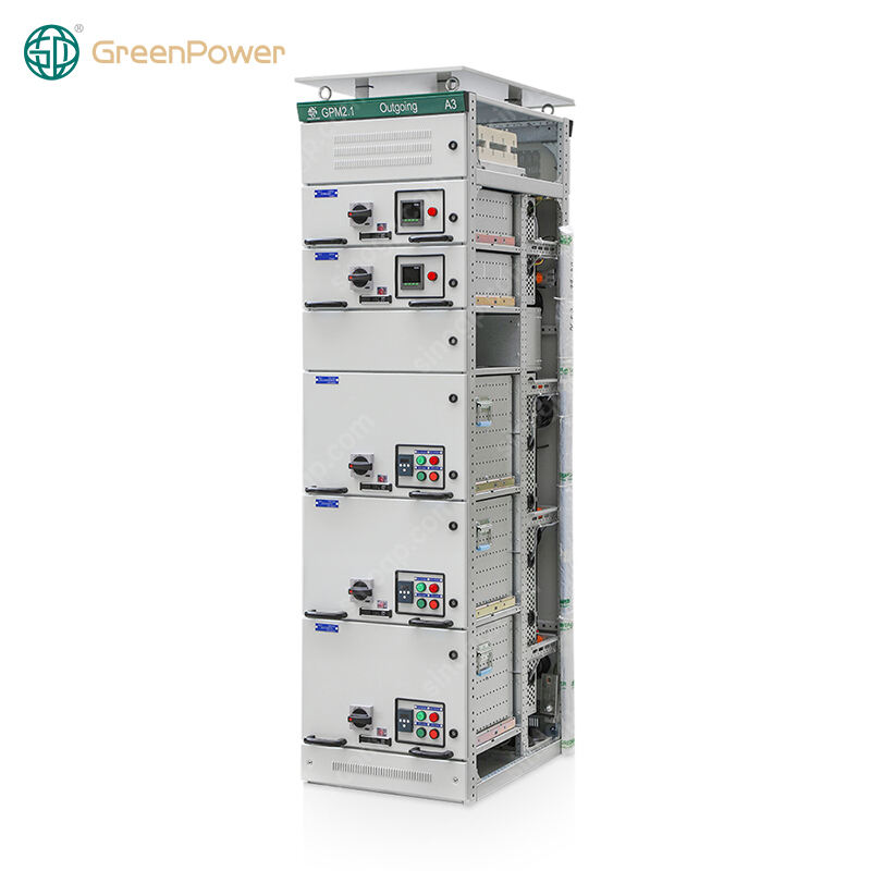
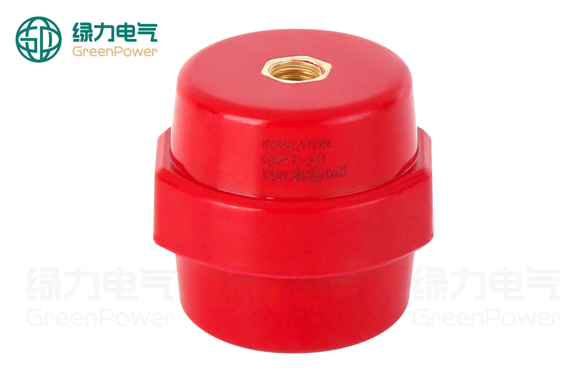
A low voltage insulator serves as a critical barrier that electrically isolates live conductors, busbars, and components from grounded structures and non‑current‑carrying parts in low‑voltage power distribution systems. Its primary protective function is to block unintended current paths, prevent leakage currents, and avoid short circuits or ground faults that could damage equipment or threaten safety. At GreenPower Electric, our low voltage insulator lineup is precision‑engineered to support stable operation in GPM1 low‑voltage switchgear cabinets, Sivacon 8PT switchboards, and various distribution assemblies. Made from high‑grade epoxy resin and composite materials, these insulators maintain excellent dielectric strength even under continuous electrical stress. They strictly comply with IEC60439, GB7251, and JB/T9661 standards, and have passed ASTA, KEMA, TÜV, and CE certifications. By providing reliable phase‑to‑phase and phase‑to‑ground isolation, the insulator effectively stops current leakage, reduces energy loss, and protects key equipment such as contactors, circuit breakers, and busbar systems from insulation degradation and electrical breakdown.
Mechanical Support and Structural Stability Enhancement
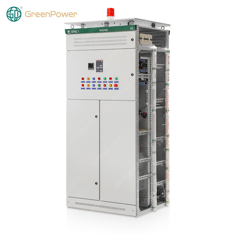
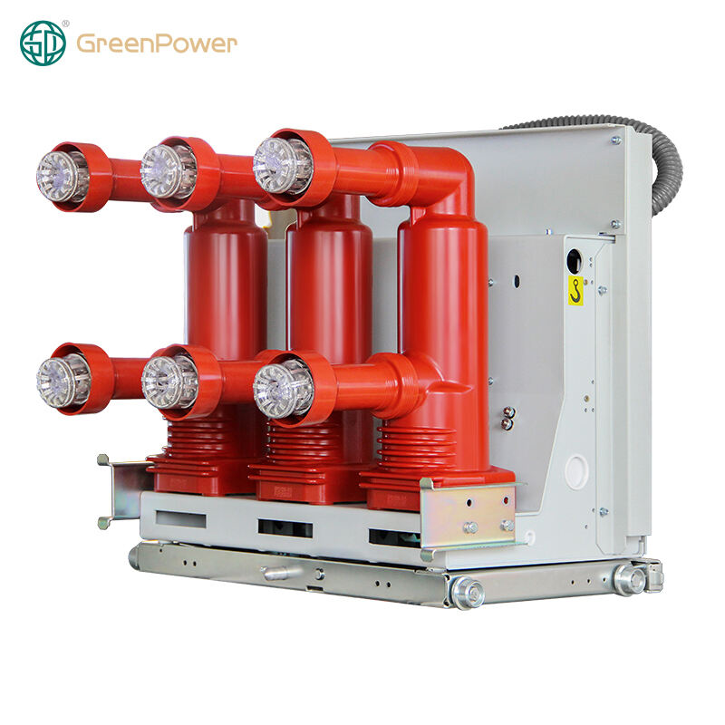
Beyond electrical protection, a low voltage insulator provides essential mechanical support and structural stability for internal components within switchgear and distribution panels. It securely holds busbars, cables, contact boxes, and connection parts in fixed positions, resisting vibration, thermal expansion, and mechanical stress during operation. Our insulator products feature robust mechanical design, high flexural strength, and reliable fastening structures, matching the demanding working conditions of industrial power distribution. They maintain stable performance in temperatures ranging from −25°C to +45°C and at altitudes up to 2000 meters, fully compatible with our low‑voltage switchgear systems. In power plants, metallurgical facilities, and oilfield applications, the insulator prevents component displacement, loose connections, and physical damage caused by long‑term operation or external impacts. By ensuring stable alignment and firm support, it reduces failures related to mechanical stress and extends the service life of the entire electrical assembly.
Environmental Adaptability and Contamination Resistance
Harsh industrial environments often expose electrical equipment to moisture, dust, chemical pollutants, and salt fog, which can weaken insulation performance and cause failures. A high‑quality low voltage insulator forms a protective layer that resists environmental erosion and maintains insulation integrity. GreenPower’s insulator products use anti‑tracking, anti‑humidity, and anti‑corrosion materials to prevent surface flashovers and insulation deterioration caused by contaminants. In coastal and industrial zones, our insulators effectively resist salt mist and chemical fumes, reducing the risk of insulation failure. During my on‑site support in Southeast Asian infrastructure projects, I observed that standard insulators required frequent cleaning due to rapid contamination buildup, while our specially designed insulators maintained stable insulation for extended periods. This environmental resilience reduces maintenance needs, minimizes unplanned downtime, and protects internal components from moisture and pollutant damage, greatly improving equipment reliability in challenging conditions.
Arc Suppression and Fault Damage Mitigation
When electrical faults such as overloads or short circuits occur, the low voltage insulator plays a key role in suppressing electric arcs and limiting fault propagation, reducing damage to surrounding components. The insulator’s high thermal stability and arc resistance slow arc development, contain electrical faults within a limited area, and prevent large‑scale equipment damage. Our insulator products are designed to work with low‑voltage circuit breakers and protection devices to improve system safety. They support quick fault isolation by maintaining insulation integrity during transient fault conditions, helping protection devices operate correctly. Industry safety authorities emphasize that reliable insulation is essential to minimize arc flash risks and protect both equipment and personnel. In practical applications, GreenPower’s insulator effectively limits arc damage, lowers maintenance costs after faults, and enhances the overall safety and stability of the power distribution system.
Long‑Term Reliability and Total Cost Optimization
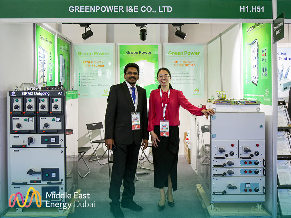
A durable low voltage insulator directly improves long‑term equipment reliability and reduces the total lifecycle cost for users. With minimal wear, excellent aging resistance, and stable performance over years of operation, high‑quality insulators reduce the frequency of replacements and maintenance. GreenPower has accumulated over 30 years of manufacturing experience, more than 150 patented designs, and 3650 completed projects, making our insulator a trusted component in global low‑voltage solutions. We provide free engineering support and after‑sales guidance to help customers achieve optimal installation and maintenance. By extending maintenance intervals, reducing failure rates, and improving system availability, our insulator helps users cut labor costs, downtime losses, and replacement expenses. As a core component supporting safe and stable operation of low‑voltage electrical systems, the insulator delivers long‑term value and strengthens the overall performance of modern industrial power distribution.

 Hot News